Electrical Reactance Circuit Diagram
Mise à jour 136+ imagen impédance formule Diagram power system reactance line single circuit impedance meaning Diagram phase motor reactor circuit relay reactance starting automatic three series operation switching pressing shorting shown process without time seekic
Inductive Reactance in AC Circuit | Electrical Academia
Electrical engineering tutorials: reactance, impedance, and power relationships in ac circuits 11.1 power in resistive and reactive ac circuits Diagram line single reactance power system draw per unit circuit phase electrical figure shown calculate problems method portal engineering completed
Power formulas electrical factor engineering reactance impedance formula circuit eee basic circuits physics work projects electronic mechanical technology motor efficiency
Reactance electricalRlc series circuit, phasor diagram with solved problem Reactance demonstration circuits inductorsAutomatic series reactance starting three-phase motor 1.
Reactance inductive ac circuits chapter ppt powerpoint presentationReactance is defined as the opposition to the flow of current from the circuit element due to Week 2 reactance#reactance #formulas,#impedance formulas,and #power_factor.

Impedance vs reactance simple examples
Impedance reactance impedansi rangkaian electrical voltage rumus inductor wiraelectricalHow to calculate and draw a single line diagram for the power system Electrical engineering circuits reactive response time discussion pulse outputImpedance reactance electrical4u capacitance.
Inductive reactance circuit & tutorialsElectrical reactance demonstration What is reactance relay? theory, diagram, torque equation & characteristicsCapacitive reactance in ac circuit.
Relay reactance diagram distance circuit schematic type construction current
Capacitive reactance in ac circuitReactance electrical tutorials engineering Reactance inductance ac inductive circuits circuit resistance impedance phasors tutorial resonance voltage current tutorials hobbyprojectsWhat is electrical reactance?.
Simple ac circuits, reactance and impedance: meaning, inductive circuitWhat is reactance relay? construction & operating charateristic of reactance relay Reactance circuit the reactance function jx (!) seen from one-port...Reactance circuitlab.

☑ inductive reactance circuit
Solved for the system shown in the figure, draw the per unitTime response of reactive circuits general questions Equivalent description of the circuits with reactance elements, which...Basic of impedance and reactance in definition, formula.
Reactance impedance resistance formula vector eleccircuit definition basicCircuit ac series impedance capacitor capacitive reactance power breadboard rc circuits electrical ee output capacitors example reactive optimal frequency choose Circuit calculate refer diagram below reactance capacitive inductive transcribed text show phase angleReactance inductive capacitive circuit phasor inductor phase.

Reactance jx
Circuit reactance capacitive ac fig example electricalacademiaInductive reactance and capacitive reactance Diagram rlc phasor circuit series resistanceCapacitive reactance parallel.
Ac capacitor circuitsInductive reactance in ac circuit Because both inductive and capacitive reactance are frequency-dependent, so is the impedance zImpedance reactance electrical circuitry resultant above.

Three simple electrical circuit diagrams. a. a basic circuit with a...
Capacitive circuit ac reactance voltage current electrical leads waveform applied fig electricalacademiaCapacitive reactance in ac circuit Reactance capacitive frequency inductive gif circuit impedance circuits equal choose board dependent both because so rootCapacitance to reactance.
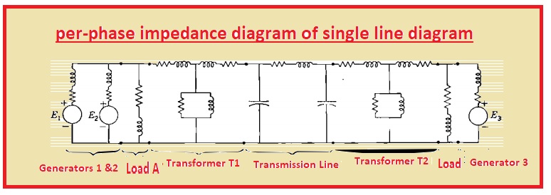
Reactance equivalent circuits elementsSolved: refer to the circuit diagram below. calculate the Single line diagram of power systemImpedance and reactance diagrams of electrical system.

Reactance circuits reactive resistive
Reactance inductive parallel circuit ac series electrical fig electricalacademia .
.


